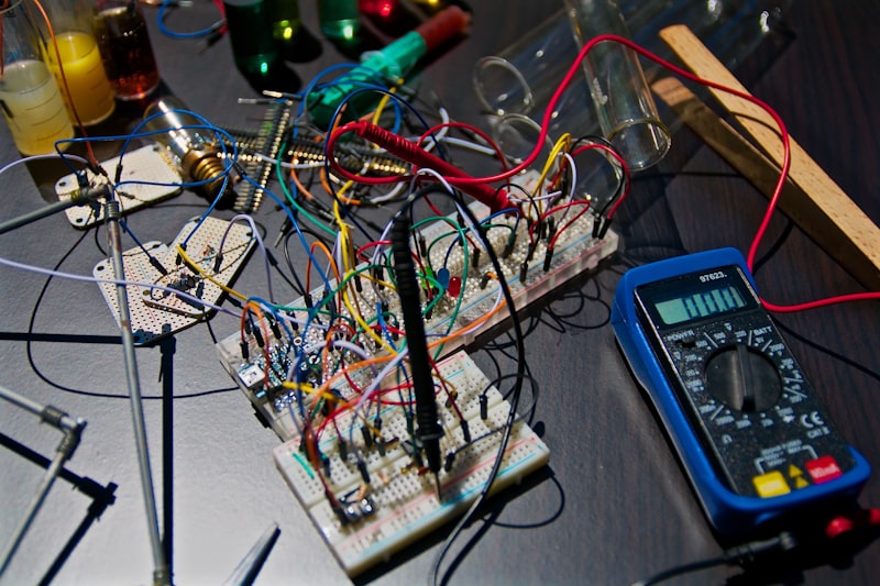
Drone boards combine fast digital logic, noisy motors, radios, sensors, and fragile analog references on a compact PCB. That means power design is always a system problem, not a single-chip problem. The regulator you choose, the current path you draw, and the way you isolate sensitive rails determine whether your controller feels robust or behaves like a random noise generator.
Think in Power Rails, Not in a Single Converter
Most UAV PCBs need at least three power domains: a battery-input or raw bus domain, a medium-current system rail such as 5V, and one or more low-noise digital or sensor rails such as 3.3V. Trying to let one converter do everything usually causes EMI, reset behavior, or thermal problems.
- Main 5V rail: often powers MCU-side peripherals, GPS, receivers, and auxiliary electronics.
- Low-noise 3.3V rail: better generated from a clean upstream rail using a suitable buck or post-regulation strategy.
- High-current or special rails: video systems, radios, and payloads may deserve their own path.
Why TPS563201 Is a Strong Starting Point
TPS563201 is a practical buck choice for UAV power trees because it offers a good balance of current capability, availability, efficiency, and layout simplicity. It fits well when you need a dependable 5V or 3.3V stage for flight electronics without moving into an unnecessarily complex power architecture.
That said, no regulator is a silver bullet. The surrounding inductor, output capacitor network, compensation expectations, and copper area decide whether the rail is genuinely clean and cool in flight.
Alternative Power ICs to Keep in Mind
| Power IC | Best Use | Main Advantage | Trade-Off |
|---|---|---|---|
| TPS563201 | Mainstream UAV system rail | Balanced efficiency and easy sourcing | Still needs disciplined layout |
| LM2596S | Higher input tolerance / legacy designs | Familiar and widely known | Larger footprint and older design style |
| MP2315 / MP2307 | Compact step-down rails | Small footprint and solid efficiency | Validate thermal and noise behavior on your board |
Layout Rules That Matter More Than the Datasheet Cover
Switching regulators punish sloppy layout. Keep the hot loop compact, place input capacitors close, and avoid sharing sensitive return current with the IMU or analog reference area. If your GPS, IMU, or RF front end sits downstream of a noisy buck rail with bad routing, software tuning will not rescue the hardware.
Board teams should review the current loop, switch node exposure, copper heat spreading, and ground strategy before prototype release. That review is often more valuable than chasing a newer regulator with slightly better headline efficiency.
How to Validate a Drone Power PCB Before Release
- Measure startup behavior at minimum and maximum battery input.
- Check ripple under idle and burst load conditions.
- Observe sensor noise with motors, radios, and logging active together.
- Run thermal checks in enclosed airflow conditions, not only open bench tests.
- Verify brownout and reset recovery after rapid throttle transitions.
Recommended Design Direction
For most drone controllers, a clean buck stage such as TPS563201 feeding a disciplined 5V or 3.3V rail is a strong starting point. Add segmentation where necessary, do not overshare current paths, and validate with the complete UAV electrical environment switched on. The most successful power designs are usually the simplest ones that still respect noise and thermal reality.
Build a cleaner UAV power tree
Need parts support for a 5V rail, compact power stage, or alternate buck regulator? Start with these common options.
Frequently Asked Questions
Only if the noise budget says you can. In many UAV boards, sensitive sensors benefit from a cleaner downstream rail or at least better isolation from noisy loads.
Often yes, provided the current budget and layout are handled correctly. The regulator choice is only half the job; board implementation decides the real result.
Poor hot-loop layout, weak decoupling placement, and unrealistic validation are more common failure causes than the controller IC itself.
It can still make sense when your design prioritizes familiarity, higher input tolerance, or easier servicing over density. Just be honest about the footprint and efficiency trade-offs.